Vertical Speed Indicator (VSI)
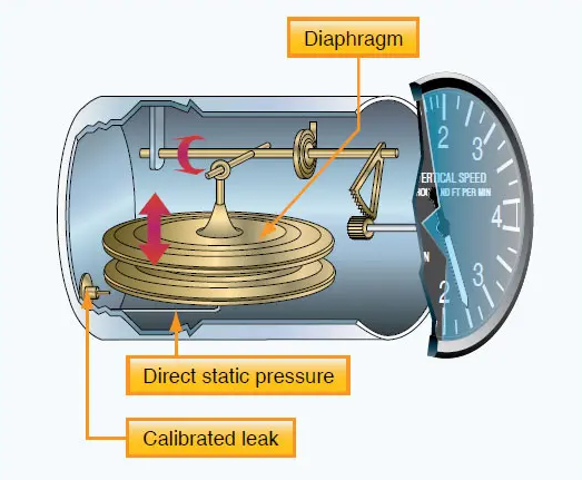
The VSI, which is sometimes called a vertical velocity indicator (VVI), indicates whether the aircraft is climbing, descending, or in level flight. The rate of climb or descent is indicated in feet per minute (fpm). If properly calibrated, the VSI indicates zero in level flight. [Figure 1-5]
Principle of Operation
Although the VSI operates solely from static pressure, it is a differential pressure instrument. It contains a diaphragm with connecting linkage and gearing to the indicator pointer inside an airtight case. The inside of the diaphragm is connected directly to the static line of the pitot-static system. The area outside the diaphragm, which is inside the instrument case, is also connected to the static line but through a restricted orifice (calibrated leak).
Both the diaphragm and the case receive air from the static line at existing atmospheric pressure. The diaphragm receives unrestricted air, while the case receives the static pressure via the metered leak. When the aircraft is on the ground or in level flight, the pressures inside the diaphragm and the instrument case are equal, and the pointer is at the zero indication. When the aircraft climbs or descends, the pressure inside the diaphragm changes immediately, but due to the metering action of the restricted passage, the case pressure remains higher or lower for a short time, causing the diaphragm to contract or expand. This causes a pressure differential that is indicated on the instrument needle as a climb or descent. When the pressure differential stabilizes at a definite ratio, the needle indicates the rate of altitude change.
The VSI displays two different types of information:
-
Trend information shows an immediate indication of an increase or decrease in the aircraft’s rate of climb or descent.
-
Rate information shows a stabilized rate of change in altitude.
The trend information is the direction of movement of the VSI needle. For example, if an aircraft is maintaining level flight and the pilot pulls back on the control yoke causing the nose of the aircraft to pitch up, the VSI needle moves upward to indicate a climb. If the pitch attitude is held constant, the needle stabilizes after a short period (6–9 seconds) and indicates the rate of climb in hundreds of fpm. The time period from the initial change in the rate of climb, until the VSI displays an accurate indication of the new rate, is called the lag. Rough control technique and turbulence can extend the lag period and cause erratic and unstable rate indications. Some aircraft are equipped with an instantaneous vertical speed indicator (IVSI), which incorporates accelerometers to compensate for the lag in the typical VSI. [Figure 1-6]
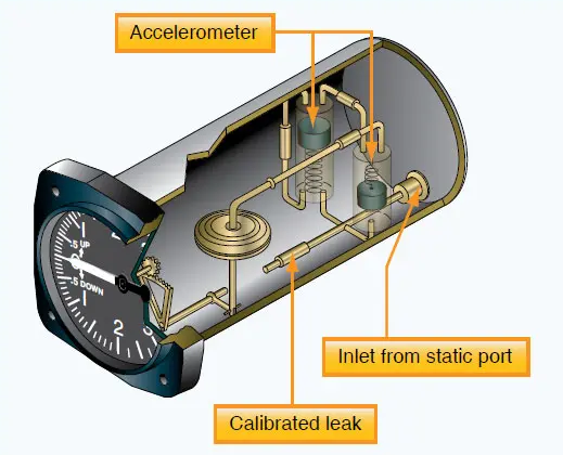
Figure 1-6. An IVSI incorporates accelerometers to help the instrument immediately indicate changes in vertical speed.
Instrument Check
As part of a preflight check, proper operation of the VSI must be established. Make sure the VSI indicates a near zero reading prior to leaving the ramp area and again just before takeoff. If the VSI indicates anything other than zero, that indication can be referenced as the zero mark. Normally, if the needle is not exactly zero, it is only slightly above or below the zero line. After takeoff, the VSI should trend upward to indicate a positive rate of climb and then, once a stabilized climb is established, a rate of climb can be referenced.
Air Speed Indicator (ASI)
The ASI is a sensitive, differential pressure gauge that measures and promptly indicates the difference between pitot (impact/dynamic pressure) and static pressure. These two pressures are equal when the aircraft is parked on the ground in calm air. When the aircraft moves through the air, the pressure on the pitot line becomes greater than the pressure in the static lines. This difference in pressure is registered by the airspeed pointer on the face of the instrument, which is calibrated in miles per hour, knots (nautical miles per hour), or both. [Figure 1-7]
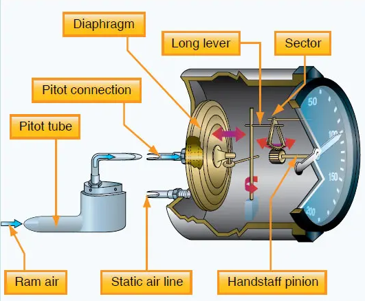
Figure 1-7. Air Speed Indicator (ASI).
The ASI is the one instrument that utilizes both the pitot, as well as the static system. The ASI introduces the static pressure into the airspeed case while the pitot pressure (dynamic) is introduced into the diaphragm. The dynamic pressure expands or contracts one side of the diaphragm, which is attached to an indicating system. The system drives the mechanical linkage and the airspeed needle.
Just as in altitudes, there are multiple types of airspeeds. Pilots need to be very familiar with each type.
-
Indicated airspeed (IAS)—the direct instrument reading obtained from the ASI, uncorrected for variations in atmospheric density, installation error, or instrument error. Manufacturers use this airspeed as the basis for determining aircraft performance. Takeoff, landing, and stall speeds listed in the AFM/ POH are IAS and do not normally vary with altitude or temperature.
-
Calibrated airspeed (CAS)—IAS corrected for installation error and instrument error. Although manufacturers attempt to keep airspeed errors to a minimum, it is not possible to eliminate all errors throughout the airspeed operating range. At certain airspeeds and with certain flap settings, the installation and instrument errors may total several knots. This error is generally greatest at low airspeeds. In the cruising and higher airspeed ranges, IAS and CAS are approximately the same. Refer to the airspeed calibration chart to correct for possible airspeed errors.
-
True airspeed (TAS)—CAS corrected for altitude and nonstandard temperature. Because air density decreases with an increase in altitude, an aircraft has to be flown faster at higher altitudes to cause the same pressure difference between pitot impact pressure and static pressure. Therefore, for a given CAS, TAS increases as altitude increases; or for a given TAS, CAS decreases as altitude increases. A pilot can find TAS by two methods. The most accurate method is to use a flight computer. With this method, the CAS is corrected for temperature and pressure variation by using the airspeed correction scale on the computer. Extremely accurate electronic flight computers are also available. Just enter the CAS, pressure altitude, and temperature, and the computer calculates the TAS. A second method, which is a rule of thumb, provides the approximate TAS. Simply add 2 percent to the CAS for each 1,000 feet of altitude. The TAS is the speed that is used for flight planning and is used when filing a flight plan.
-
Groundspeed (GS)—the actual speed of the airplane over the ground. It is TAS adjusted for wind. GS decreases with a headwind and increases with a tailwind.
Airspeed Indicator Markings
Aircraft weighing 12,500 pounds or less, manufactured after 1945, and certificated by the FAA are required to have ASIs marked in accordance with a standard color-coded marking system. This system of color-coded markings enables a pilot to determine at a glance certain airspeed limitations that are important to the safe operation of the aircraft. For example, if during the execution of a maneuver, it is noted that the airspeed needle is in the yellow arc and rapidly approaching the red line, the immediate reaction should be to reduce airspeed.
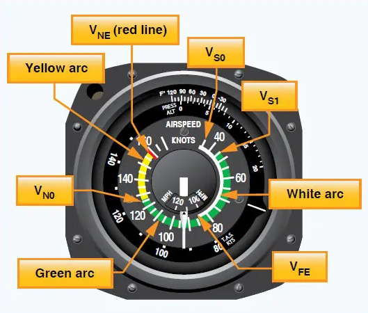
Figure 1-8. Single Engine Air Speed Indicator (ASI).
As shown in Figure 1-8, ASIs on single-engine small aircraft include the following standard color-coded markings:
-
White arc—commonly referred to as the flap operating range since its lower limit represents the full flap stall speed and its upper limit provides the maximum flap speed. Approaches and landings are usually flown at speeds within the white arc.
-
Lower limit of white arc (VS0)—the stalling speed or the minimum steady flight speed in the landing configuration. In small aircraft, this is the power-off stall speed at the maximum landing weight in the landing configuration (gear and flaps down).
-
Upper limit of the white arc (VFE)—the maximum speed with the flaps extended.
-
Green arc—the normal operating range of the aircraft. Most flying occurs within this range.
-
Lower limit of green arc (VS1)—the stalling speed or the minimum steady flight speed obtained in a specified configuration. For most aircraft, this is the power-off stall speed at the maximum takeoff weight in the clean configuration (gear up, if retractable, and flaps up).
-
Upper limit of green arc (VN0)—the maximum structural cruising speed. Do not exceed this speed except in smooth air.
-
Yellow arc—caution range. Fly within this range only in smooth air and then only with caution.
-
Red line (VNE)—never exceed speed. Operating above this speed is prohibited since it may result in damage or structural failure.
Other Airspeed Limitations
Some important airspeed limitations are not marked on the face of the ASI, but are found on placards and in the AFM/ POH. These airspeeds include:
-
Design maneuvering speed (VA)—the maximum speed at which the structural design’s limit load can be imposed (either by gusts or full deflection of the control surfaces) without causing structural damage. It is important to consider weight when referencing this speed. For example, VA may be 100 knots when an airplane is heavily loaded, but only 90 knots when the load is light.
-
Landing gear operating speed (VLO)—the maximum speed for extending or retracting the landing gear if flying an aircraft with retractable landing gear.
-
Landing gear extended speed (VLE)—the maximum speed at which an aircraft can be safely flown with the landing gear extended.
-
Best angle-of-climb speed (VX)—the airspeed at which an aircraft gains the greatest amount of altitude in a given distance. It is used during a short-field takeoff to clear an obstacle.
-
Best rate-of-climb speed (VY)—the airspeed that provides the most altitude gain in a given period of time.
-
Single-engine best rate-of-climb (VYSE)—the best rate-of-climb or minimum rate-of-sink in a light twin-engine aircraft with one engine inoperative. It is marked on the ASI with a blue line. VYSE is commonly referred to as “Blue Line.”
-
Minimum control speed (VMC)—the minimum flight speed at which a light, twin-engine aircraft can be satisfactorily controlled when an engine suddenly becomes inoperative and the remaining engine is at takeoff power.
Instrument Check
Prior to takeoff, the ASI should read zero. However, if there is a strong wind blowing directly into the pitot tube, the ASI may read higher than zero. When beginning the takeoff, make sure the airspeed is increasing at an appropriate rate.