Gyroscopic Flight Instruments
Heading Indicator
The heading indicator is fundamentally a mechanical instrument designed to facilitate the use of the magnetic compass. Errors in the magnetic compass are numerous, making straight flight and precision turns to headings difficult to accomplish, particularly in turbulent air. A heading indicator, however, is not affected by the forces that make the magnetic compass difficult to interpret. [Figure 1-25]
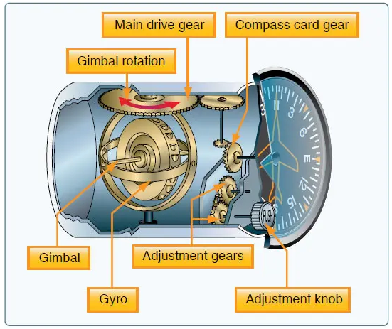
Figure 1-25. A heading indicator displays headings based on a 360° azimuth, with the final zero omitted. For example, “6” represents 060°, while “21” indicates 210°. The adjustment knob is used to align the heading indicator with the magnetic compass.
The operation of the heading indicator depends upon the principle of rigidity in space. The rotor turns in a vertical plane and fixed to the rotor is a compass card. Since the rotor remains rigid in space, the points on the card hold the same position in space relative to the vertical plane of the gyro. The aircraft actually rotates around the rotating gyro, not the other way around. As the instrument case and the aircraft revolve around the vertical axis of the gyro, the card provides clear and accurate heading information.
Because of precession caused by friction, the heading indicator creeps or drifts from its set position. Among other factors, the amount of drift depends largely upon the condition of the instrument. If the bearings are worn, dirty, or improperly lubricated, the drift may be excessive. Another error in the heading indicator is caused by the fact that the gyro is oriented in space, and the Earth rotates in space at a rate of 15° in 1 hour. Thus, discounting precession caused by friction, the heading indicator may indicate as much as 15° error per every hour of operation.
Some heading indicators referred to as horizontal situation indicators (HSI) receive a magnetic north reference from a magnetic slaving transmitter and generally need no adjustment. The magnetic slaving transmitter is called a magnetometer.
Attitude and Heading Reference System (AHRS)
Electronic flight displays have replaced free-spinning gyros with solid-state laser systems that are capable of flight at any attitude without tumbling. This capability is the result of the development of the Attitude and Heading Reference System (AHRS).
The AHRS sends attitude information to the PFD in order to generate the pitch and bank information of the attitude indicator. The heading information is derived from a magnetometer that senses the earth’s lines of magnetic flux. This information is then processed and sent out to the PFD to generate the heading display. [Figure 1-26]
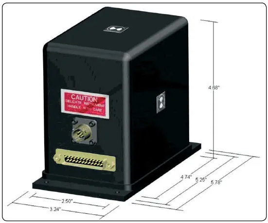
Figure 1-26. Attitude and heading reference system (AHRS).
The Flux Gate Compass System
As mentioned earlier, the lines of flux in the Earth’s magnetic field have two basic characteristics: a magnet aligns with them, and an electrical current is induced, or generated, in any wire crossed by them.
The flux gate compass that drives slaved gyros uses the characteristic of current induction. The flux valve is a small, segmented ring, like the one in Figure 1-27, made of soft iron that readily accepts lines of magnetic flux. An electrical coil is wound around each of the three legs to accept the current induced in this ring by the Earth’s magnetic field. A coil wound around the iron spacer in the center of the frame has 400 Hz alternating current (AC) flowing through it. During the times when this current reaches its peak, twice during each cycle, there is so much magnetism produced by this coil that the frame cannot accept the lines of flux from the Earth’s field.
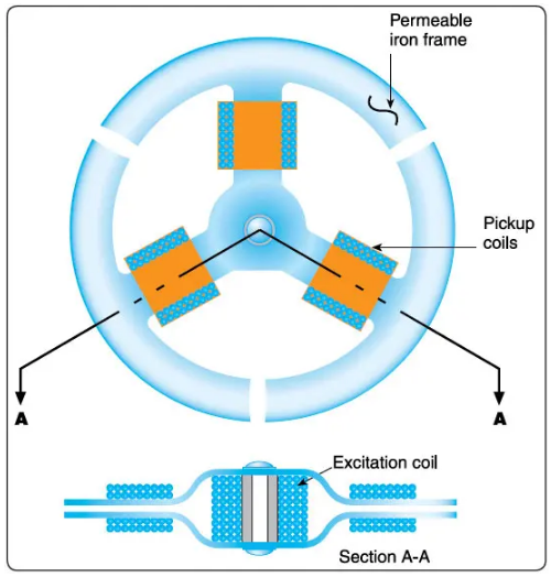
Figure 1-27. The soft iron frame of the flux valve accepts the flux from the Earth’s magnetic field each time the current in the center coil reverses. This flux causes current to flow in the three pickup coils.
As the current reverses between the peaks, it demagnetizes the frame so it can accept the flux from the Earth’s field. As this flux cuts across the windings in the three coils, it causes current to flow in them. These three coils are connected in such a way that the current flowing in them changes as the heading of the aircraft changes. [Figure 1-28]
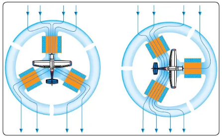
Figure 1-28. The current in each of the three pickup coils changes with the heading of the aircraft.
The three coils are connected to three similar but smaller coils in a synchro inside the instrument case. The synchro rotates the dial of a radio magnetic indicator (RMI) or a HSI.
Remote Indicating Compass
Remote indicating compasses were developed to compensate for the errors and limitations of the older type of heading indicators. The two panel-mounted components of a typical system are the pictorial navigation indicator and the slaving control and compensator unit. [Figure 1-29] The pictorial navigation indicator is commonly referred to as an HSI.
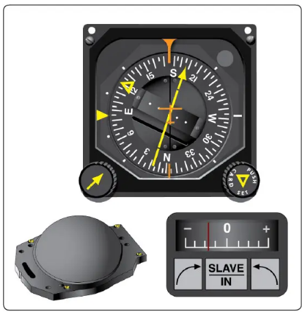
Figure 1-29. Pictorial navigation indicator (HSI, top), slaving meter (lower right), and slaving control compensator unit (lower left).
The slaving control and compensator unit has a push button that provides a means of selecting either the “slaved gyro” or “free gyro” mode. This unit also has a slaving meter and two manual heading-drive buttons. The slaving meter indicates the difference between the displayed heading and the magnetic heading. A right deflection indicates a clockwise error of the compass card; a left deflection indicates a counterclockwise error. Whenever the aircraft is in a turn and the card rotates, the slaving meter shows a full deflection to one side or the other. When the system is in “free gyro” mode, the compass card may be adjusted by depressing the appropriate heading-drive button.
A separate unit, the magnetic slaving transmitter, is mounted remotely, usually in a wingtip to eliminate the possibility of magnetic interference. It contains the flux valve, which is the direction-sensing device of the system. A concentration of lines of magnetic force, after being amplified, becomes a signal relayed to the heading indicator unit, which is also remotely mounted. This signal operates a torque motor in the heading indicator unit that processes the gyro unit until it is aligned with the transmitter signal. The magnetic slaving transmitter is connected electrically to the HSI.
There are a number of designs of the remote indicating compass; therefore, only the basic features of the system are covered here. Instrument pilots must become familiar with the characteristics of the equipment in their aircraft.
As instrument panels become more crowded and the pilot’s available scan time is reduced by a heavier flight deck workload, instrument manufacturers have worked toward combining instruments. One good example of this is the RMI in Figure 1-30. The compass card is driven by signals from the flux valve, and the two pointers are driven by an automatic direction finder (ADF) and a very high frequency (VHF) omni-directional radio range (VOR).
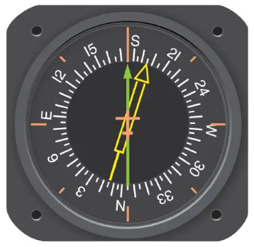
Figure 1-30. Driven by signals from a flux valve, the compass card in this RMI indicates the heading of the aircraft opposite the upper center index mark. The green pointer is driven by the ADF.
Heading indicators that do not have this automatic northseeking capability are called “free” gyros and require periodic adjustment. It is important to check the indications frequently (approximately every 15 minutes) and reset the heading indicator to align it with the magnetic compass when required. Adjust the heading indicator to the magnetic compass heading when the aircraft is straight and level at a constant speed to avoid compass errors.
The bank and pitch limits of the heading indicator vary with the particular design and make of instrument. On some heading indicators found in light aircraft, the limits are approximately 55° of pitch and 55° of bank. When either of these attitude limits is exceeded, the instrument “tumbles” or “spills” and no longer gives the correct indication until reset. After spilling, it may be reset with the caging knob. Many of the modern instruments used are designed in such a manner so that they do not tumble.
An additional precession error may occur due to a gyro not spinning fast enough to maintain its alignment. When the vacuum system stops producing adequate suction to maintain the gyro speed, the heading indicator and the attitude indicator gyros begin to slow down. As they slow, they become more susceptible to deflection from the plane of rotation. Some aircraft have warning lights to indicate that a low vacuum situation has occurred. Other aircraft may have only a vacuum gauge that indicates the suction.
Instrument Check
As the gyro spools up, make sure there are no abnormal sounds. While taxiing, the instrument should indicate turns in the correct direction, and precession should be normal. At idle power settings, the gyroscopic instruments using the vacuum system might not be up to operating speeds and precession might occur more rapidly than during flight.